Ah. Hmm. Yes. Draw up a chair, fictional young person, and I'll tell you a tale about one Sir Isaac Newton. First, though, an account, a frame of reference written by a select few hermits, gate-keepers of knowledge from across the globe, driven insane by their own reclusion and sense of self-worth:
http://www.wikipedia.org/Isaac_Newton
Quite a man. Being the devil-worshipper he was, Sir Isaac Newton was driven to frequent fits of madness, touched by the hand of Satan. Or by alcohol, it's possible. During these fits of madness, Isaac would storm about his well-appointed villa and throw things all over the place until the demon within him subsided and his frail physical form could no longer lift anything breakable to throw.
One terrible time in particular occurred while his seven-year-old niece was visiting. She entered the room he was raging in, unaware of his state, and asked him sweetly why roses smell so lovely. Isaac Newton, drowning in his delusions (or possibly Brandy), thought her to be an Imp from Tartarus, so he grabbed her and threw her out the third-story window. And that's when he had his revelation. For as he watched her small, petticoated body fall to the ground below in slow motion, he wondered at the force that drew her earthwards. He wondered, and later at her funeral, cursed that force, vowing revenge against it for killing his niece. And that force is precisely what inspired this synthesizer.
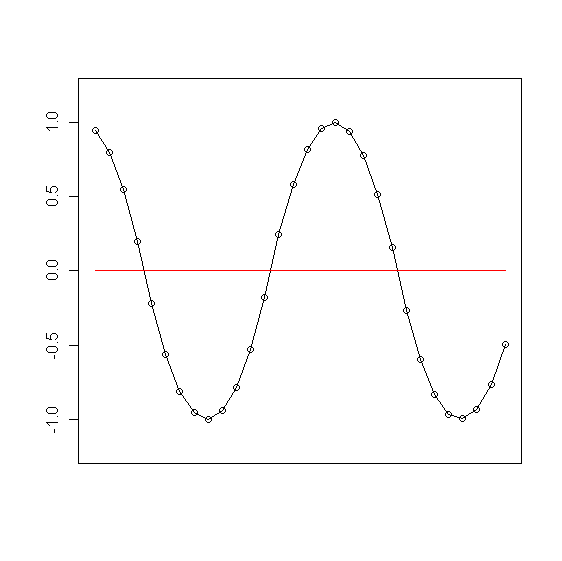
You see, I'm a very visual kind of person, and an audio waveform to me looks like the path some kind of ball might take if a bunch of wierd, physical forces were acting upon it. Actually, with a more simplified audio waveform, it could be the path a ball might take just going up and down if that path were mapped on a sheet of paper that was moving right-to-left over time. In fact, that force *could* be gravity if gravity switched every time the ball passed through some invisible horizonal plane (like say, oh, DC?). If that were the case, the wave form would almost (almost) look like a sinewave, right?
That's actually the gist of it, right there, and the default settings for The Newtonator make that exact waveform. Of course, gravity is adjusted for each note's frequency so that it's lighter for low notes and heavier for high notes. Pretty simple, right?
But this is a synthesizer, and I want it to make sounds both beautiful and ugly, from wind blowing through the trees to seals mating on a run-away dump truck. So how about that invisible plane? We can modulate that, and we'll call if the Floor. We can modulate gravity too, while we're at it. We can also make gravity scale exponentially the farther away the ball is from the floor. Hmm, our ball is going to start exceeding the bounds of a normal 32 bit audio waveform, so let's call those bounds the Ceiling, and lets make the ball do different stuff when it hits the ceiling. Of course, with all this modulation going on, the original intended frequency may get lost in the shuffle; let's mess with the velocity periodically, matching that intended frequency.
That's not even all of it, but let's just recap in a less conversational and more mathematical manner. We've got the bounds of each sample value at 1.0 and -1.0 (Ceiling), we've got our invisible plane at 0.0 (Floor), and our algorithm involves position, velocity, and acceleration (gravity). So, the formula (according to Newton) to compute any object's position when dropped from any given hight after T amount of time is:
...where v is the initial velocity and g is gravity. Computing this on a per-sample basis means that T = 1, and the position it's dropped from is the previous sample value, so when we compute each sample value our algorithm code actually looks like this:
Example 1. Main Algorithm
	currSamp = prevSamp + prevVeloc + (grav / 2);
	currVeloc = currVeloc + grav;

	/* Output currSamp as the value of the current sample in the audio
	frame... */

	/* Switch the gravity once it crosses the floor */
	if ((grav < 0 && currSamp < 0) || (grav > 0 && currSamp >= 0))
	    grav *= -1;

	prevVeloc = currVeloc;
	prevSamp = currSamp;
Again, pretty simple, and all the previously mentioned additions really aren't that big of a deal either. One thing to note is that The Newtonator computes each channel in stereo independently, so our left and right channels have their own values for gravity, velocity, etc. It's twice as expensive, computationally speaking, but any slight deviation in the values in that algorithm quickly turns into nice audible differences, and we can also do stuff like periodically switching velocity values between the channels.
Now that you understand the basic algorithm and some of the tweaks I've introduced, let's go over each setting in detail and discuss what they do.
This section covers the main sound-making capabilities of The Newtonator, sans any modulation of the main elements (covered in later in the following sections). The sections also, you'll note, correspond to the tabs in the Newtonator's user interface, so it's easy-peasy to find any control that happens to be mystifying you.
- Amp. Env.
This set of controls is simply amazing. They shape the amplitude of each note over time! You will never see the likes of these controls in any other synthesizer.
- Attack, Decay, Release
The stage times, in seconds, for an ADSR envelope that is applied to the note's amplitude. They go all the way to ten seconds each, and transition functions are all linear. Nothing real fancy.
- Sustain
Sustain level of the ADSR envelope, as a ratio of the max amplitude of the note.
- Clip Wobble
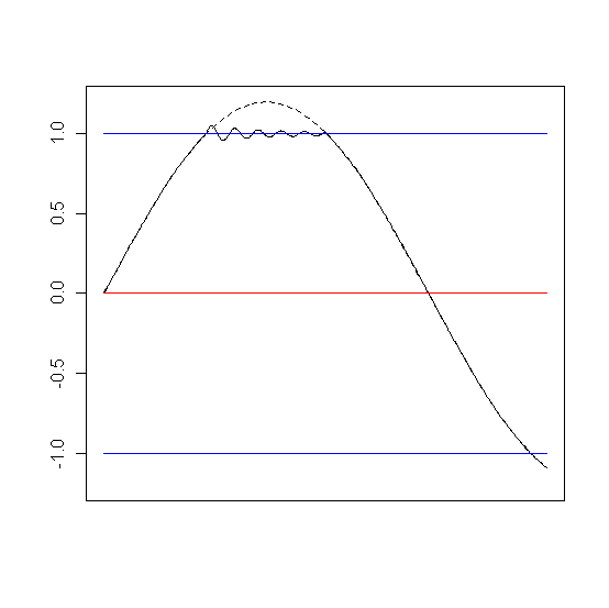
This set of parameters controls clipping wobble. That's my fancy name for a bit of embelishment the Newtonator adds to audio clipping. Allow me to illustrate.
Clipping Wobble happens after all the main algorithm computations are finished and the synth thinks it has a final wave form. The wobble algorithm is keeping track of the velocity separately, and when the main algorithm clips the signal in any way the wobble algorithm kicks in. It uses the velocity and its own sine wave generator to oscillate the wave form, centered right on the clipping limit and scaled based on the velocity; the higher the velocity, the greater the initial amplitude of this oscillation. It scales down relatively quickly, though, so the effect can be quite subtle. It's all, of course, configurable, and can get as audible as you want it.
To better understand the admiteddly obscurely-named parameters for clip wobble, the below code illustrates how the wobble is calculated:
Example 2. Clip Wobble Algorithm
			  StkFloat scale = (1.0 - getWobbleScale(chan));
			  StkFloat retSample = 0;
			  StkFloat sine = _wobbleWav[chan].tick();
			  StkFloat clip = (currSample > 0 ? MAX_VAL : MIN_VAL);

			  retSample = clip + (_pPrevVeloc[chan] * _a[chan] * sine * getWobbleScale(chan) * 8);
			  _a[chan] -= (getWobbleB(chan) * _a[chan]);

			  return retSample * scale;
Ok, so that clearly isn't a very understandable example for almost everyone except programmers. So we have two options. One, I could try to explain all of this code using metaphores and parables, or two, you could all go out and learn C++. Option two is much less of a headache for me and I'm much less likely to loose the small shred of sanity I have left, so that's what I'm going with. Report back when you're learned it all and you're ego has grown three sizes too large.
Ok ok, fine, keep reading, I'll explain as best as I can. Sheesh...
- Scale
getWobbleScale(chan)in Example 2, “Clip Wobble Algorithm”. This parameter controls the overall amplitude of the oscillation; think of this as a kind of volume knob for clip wobble in total. You may notice that when this parameter is turned down, the overall volume of the synthesizer seems to increase. That's because the control waveform (the one that's using Example 1, “Main Algorithm”) needs to make a little room for whatever clip wobble oscillation will happen. If very little happens, then very little room needs to be made and the control waveform can be louder as a result.- A
_a[chan]in Example 2, “Clip Wobble Algorithm”. This parameter affects the initial amplitude of the oscillation. In the above code, _a[chan] is set to this number whenever clipping is first detected in the control waveform (this happens in another piece of code, not above). Thereafter, _a[chan] is scaled down incrementally, based on B.- B
getWobbleB(chan)in Example 2, “Clip Wobble Algorithm”. B helps scale down the amplitude of the clipping oscillation over a short period of time. The smaller this value is, the longer the oscillation will be audible. Again, though, this is still over a very short period of time.- Timbre
Affects
_wobbleWav[chan]in Example 2, “Clip Wobble Algorithm”._wobbleWav[chan]is the sine wave generator for the clipping oscillation. When clipping is first detected, this variable's frequency is set to this value (more or less), which is then multiplied by the current velocity of the control waveform. So, the faster the control waveform is oscillating, the higher the clipping frequency will be (generally speaking).
- Velocity
These parameters all affect the velocity in some form or fashion.
- Switch Velocity
When flagged, this parameter tells the algorithm to switch the velocity values of each channel (remember, each channel has its own synth engine) at an interval equal to the current note's frequency. This has a more pronounced effect with Channel Separation
- Velocity Reset
At intervals equal to the current note's frequency, the current velocity value will be multiplied by this number. Since this number can be negative, this can drastically affect the path of the waveform and force the algorithm's fundamental frequency back to the intended note's frequency.
For instance, if our ball was headed downward, then when the note's frequency period ocurred and Velocity Reset was at -1, the ball would start to head back upwards at equal velocity, almost like it had bounced on a hard surface. The gravity is the same, mind you (if the ball hasn't crossed the floor, that is), so the ball will eventually head back down again, but these periodic changes in velocity are very audible and can be used to force the sound to adhere to the current note's frequency.
- Velocity Delay
This parameter will put a delay on the signal of the velocity for the given number of samples for purposes of computing the main algorithm only. That means this delay isn't "remembered" in the rest of the algorithm, so, for instance, if one uses Velocity Ring Mod., that velocity value being used will not be delayed.
- Velocity Sample And Hold
This parameter will hold the current value of the velocity for the given number of samples, then set the velocity value to what it is supposed to be, ad infinitum. However, the number of samples is scaled according to the current note's frequency, so the higher the frequency, the shorter the sample and hold affect will be. Like Velocity Delay, this effect on the velocity is only used for computing the main algorithm only, not for all the various effects and mods, so it won't, for instance, be audible in Velocity Ring Mod..
- Velocity Ring Mod.
This parameter affects how much of the final audio signal will be multiplied by the velocity signal. The velocity signal is scaled appropriately to its own maximum value and so is not affected by the actual velocity values in its own signal path.
- Misc.
This set of parameters covers other miscellanious functionality.
- Ceiling Behavior
This dropdown box lets you choose how the ceiling affects the algorithm. The following items are your choices:
- Ext. Clip
The audio signal is allowed to wander outside the bounds of a normal waveform, and is then clipped at the very end of the process, right before the audio signla is written to the LV2 audio port.
- Int. Clip
As Ext. Clip, but the audio signal clipping is visible to the main algorithm. So, in Example 1, “Main Algorithm”,
prevSampcan never be greater than the bounds of a normal audio waveform. This can have a drastic effect on the sound of the audio signal being produced and, in general, makes for a more "tame" sound.- Bounce
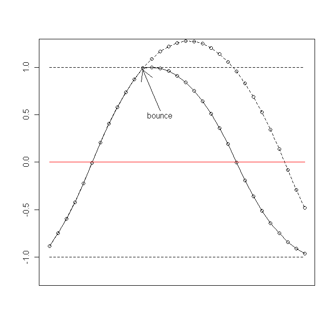
The audio signal is never allowed to exceed the bounds of a normal audio waveform, but instead of being clipped, the algorithm alters the velocity with Ceiling Bounce whenever this limit is reached.
The above illustrates our ball bouncing off of the ceiling, with Ceiling Bounce set at or near -1. The dashed ball path illustrates the path the ball would have taken had it not bounced into the ceiling.
- Ceiling Bounce
When Ceiling Behavior is set to “Bounce”, this control is enabled and determines how hard or soft the ball will bounce back off of the ceiling. If it's greater then zero, our ball will rebound harder than when it hit the ceiling (as if the ceiling were made out of rubber). If it's less than zero, it will bounce back more slowly (as if it had hit a soft surface). If it's at or near -1, the rebound velocity will almost be zero, so it completely retards the ball's momentum.
- Gravity Readjust
When flagged this will basically enable the main algorithm to adjust velocity and position values at a finer level of detail whenever the signal crosses the floor. It does this in order to more accurately express the intended note frequency, at the expense of more computing time. However, this only happense whenever the floor is crossed, so the extra computing time is fairly minimal. Also, note that this adjustment does not take into consideration any of the many modulations and adjustments to the velocity, gravity, and floor outside of the main computation, so its utility is fairly limited as far as enabling more accurate frequency representations in the audio signal.
- Channel Separation
The greater this value, the more audible the differences will be between the left and right channel signals. It does this by introducing variances in many of the synth parameters between each audio channel.
This section covers parameters that govern the modultation of gravity. If you'll recall, gravity is set depending on whatever note is being played. However, the gravity can be modulated around this target gravity value, creating all manner of interesting effects.
- Envelope
As Amp. Env., except this envelope (when enabled) is applied to the gravity modulation signal.
- Frequency
This set of parameters controls the frequency of the gravity modulation signal.
- Follow Frequency
Indicates that the frequency of the modulation should be based on the note's intended frequency. Note that this switches setting the frequency between an absolute value and a note-based value, so depending on this flag, certain controls below may be disabled.
- Freq. Drift
This value will multiply the modulation frequency by the given amount plus one, up or down. This can introduce slight variations in the note frequency versus the modulation frequency, producing an audible beating in the audio signal. Note that this multiplication of the frequency happens in tandem with Freq. Divider.
- Freq. Divider
This parameter scales the frequency up or down by the given number of octaves.
- Absolute Frequency
Sets the frequency to the value indicated here. Note that fractional values are possible, enabling an LFO signal.
- Misc
Miscellaneous settings pertaining to gravity modulation or manipulation.
- Gravity Scaling
This parameter will scale the gravity up exponentially the farther the ball is from the floor.
- Depth
Determines how much gravity modulation will be applied, as a multiplier to the gravity modulation waveform. Once this is set to anything greater than zero, the Frequency and Envelope controlls will be enabled.
- DC Offset
The gravity modulation waveform oscillates from -1 to 1. This is then multiplied by Depth, then the DC Offset is addeded to the signal as a constant. The resulting signal is then multiplied to the actual gravity value being used, and there you have our gravity modulation. Yay! So, to recap mathematically:
So, one use of DC Offset could be to increase or decrease the gravity directly when Depth is zero. This in turn will directly affect the frequency of each note played. Adjusting DC Offset will also dictate whether the gravity modulation will increase and decrease it in one direction, or make it switch directions altogether. Neato.
- Grav. Mod. Waveform
This parameter dictates the shape of the waveform used to modulate the gravity. Your choices are:
Sine
Saw (decending)
Square
Impulse
Noise (unaffected by the frequency settings)
External (see below)
External is special. Primarily, it may not even be available as a waveform if the synth wasn't compiled with that option. In that case, just ignore all of this rabble and read the next section or whatever.
If it is available, The Newtonator will expose two audio inputs as a Jack client. One of them (labeled “lft/rgt_gmod_input”) will route to the “GModWaveform” signal illustrated in Equation 2, “Gravity Modulation” whenever External is selected as the waveform. Note that Envelope and Frequency will have no effect if an external waveform is being used.
Using an external waveform, then, allows you to use any waveform that can be routed into the Jack inputs as a modulating waveform. Nifty, eh? Hook your microphone up, route the recorded audio into the inputs and voila! Voice modulation of the gravity.
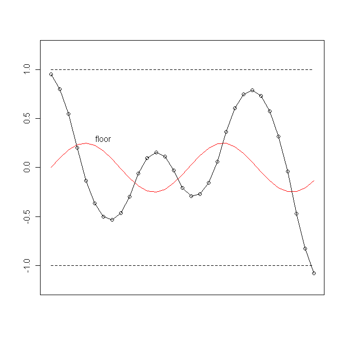
Floor modulation just makes the floor our ball is falling through modulate according to a specified waveform, at a specified frequency and amplitude. The following figure is a good example of the effect this can have on the audio signal.
- Envelope
As Amp. Env., except this envelope (when enabled) is applied to the floor modulation signal.
- Frequency
As Frequency, except the frequency is applied to the floor modulation signal.
- Misc.
Miscellaneous settings pertaining to floor modulation or manipulation.
- Floor Scaling
This parameter determines how much the floor signal will modulate. Once this parameter is set to anything greater than zero, the Envelope and Frequency controlls will be enabled.
- Dead Zone
The Dead Zone defines an area between the ceilings in which gravity has no effect. That is, the ball will cease to accelerate once it enters this area, though it will maintain its current velocity until it escapes the Dead Zone, at which point gravity will kick back in.
The Dead Zone will, in effect, make the audio waveform kind of like a triangle waveform, making our ball travel up or down in a very straight trajectory while it's in the Dead Zone. Note, however, that this is less likely to have an audible effect the faster our ball is traveling between the ceilings.
- Floor Waveform
Just like Grav. Mod. Waveform, but it applies to the floor.
- Floor/Ceiling Reflect
This one perhaps isn't named very well, but it's more descriptive than Matilda, at any rate. What this control does is to make the ceilings modulate, just like the floor. So, when this control is set above 0, all the frequency and envelope settings will be enabled (since they're now applicable).
What this means, then, is that the sound waveform can do all sorts of crazy things it likes, and it will (more than likely) clip all over the place, but the clipping will conform to the modulation defined in this section. This is another good way to force melodicity on the waveform.


